
Testing of RS232 control cables for installers
Summary:
Despite the increase in control via ethernet the use of RS232 is widespread in integrated AV systems and the connection of these control cables and testing of the falls within the remit of the installation engineer. However many AV engineers lack the knowledge to test and fault find these connections and hence cabling problems are the number one cause of problems at the programming stage. The testing of Video and Audio signal routing throughout a system is common and more widely understood and this article attempts to provide a toolbox of methods for simple testing of RS232 cabling within a system.
The methods below require no control system training and are applicable to any RS232 system.
Pre-amble:
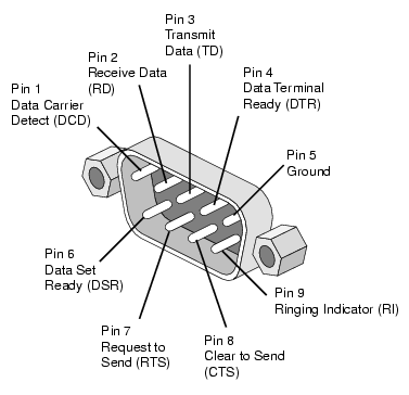
To effectively install and test a cable for RS232 control you need to know what the pin out specification for the device that is being controlled and the pin out specification for the controller.
This information may have been found by the system designer in which case you might find it in your job specific method statement, cable listing or schematic drawing. If you don’t have this information you cant install the RS232 cabling and can either install a standard straight through RS232 cable and rely on adaptors at the controlled device end, speak to the system designer to clarify this information or find out the information yourself from the manufacturer documentation.
Method 1: Voltage test on RX / TX
It is possible to carry out a simple test on the GND, TX and RX of a connected RS232 link with both the controller and the controlled device connected.
e.g.
And AMX NI2100 controlling a Panasonic Projector.
AMX Module documentation provides the following cable specification:
AMX NI (DB-9 Female) – Panasonic (DB-9 Male)
5(GND)———————5 (GND)
2 (RXD)———————2 (TXD)
3 (TXD)———————3 (RXD)
Testing at the projector end (Male db9)
With both devices connected:
We should see a negative voltage on pin 2 and 3.
If both pins remain at 0V it is likely that RX and TX are incorrectly crossed.
With the projector disconnected:
When the projector is disconnected we would see only a voltage on pin 3.
Method 2: Loopback Test
Using a loopback is a great way of testing installed RS232 wiring. Put simply by connecting the RX and TX pins at the remote end we can test the continuity and correct pin wiring of the cabling throughout its length of installation.
A loopback connector should be a Female DB9 with pin’s 2 and 3 connected and pin’s 7 and 8 connected.
A loopback test is carried out simply by sending some data from a terminal software running on a pc. As the RX and TX pins are connected if the wiring is continuous then the transmitted data loops back onto the rx pin of the PC and the data sent is received back by the PC.
A detailed tutorial of this simple test can be found here http://www.ni.com/tutorial/3450/en/#toc3
This test is however limited in that it will not show up errors of RX and TX being crossed over incorrectly.
Method 3: Testing cabling using Manufacturer Software tools
This involves testing communications by using a manufacturer provided software to communicate with the device hence proving the control cabling.
Not all devices have a software application but most do and I have included some of the common ones below:
Software can be found on the manufacturer’s website and is often provided on disc when a product is shipped.
BARCO Projector Toolset
NEC Screens
PD Comms tool http://www.necdisplay.com/support-and-services/pdcommstool/downloads
Samsung Screens
MDC Multiscreen Control Software
multiscreen.sharewarejunction.com
Kramers Switchers
Protocol 2000
http://www.kramerelectronics.com/support/download.asp?f=35567
Protocol 3000
http://www.kramerelectronics.com/products/model.asp?pid=2870
Extron Switchers
http://www.extron.com/download/dltrack.aspx?file=MATRIX_SW_v8x4.exe&id=67589
AMX Switchers
APControl 3.0.1.1
Method 4: Simple device control
When no manufacturer tool exists using a simple command terminal is the only way of proving correct wiring from AV controller to 3rd party device.
To do this test a computer running a terminal program should be connected temporarily in place of the AV controller this way the installed cabling is tested entirely. The object of the test is to demonstrate 1 way control over the controlled device over RS232 by seeing visual feedback on the device. Where 2-way control is required the test should also prove that the controlled device has responded with some data on the terminal.
Example:
LG Screens: RS232 Setting 9600,0,8,1
Command: ASCII ‘ka 1 1’ Action: Turns screen on from standby
Command:ASCII ‘ka 1 0’ Action: Turns screen off to standby
You can download the pdf version here